Setting up a basic two-computer wired LAN connection in Linux can sometimes be a challenge due to the lack of straightforward examples. If you find yourself in need of connecting two machines together using a LAN cable, the following steps will guide you through the process.
On Computer A, open a terminal and enter the following command:
sudo ip addr add 192.168.20.1/24 dev eth0
On Computer B, open a terminal and enter the following command:
sudo ip addr add 192.168.20.2/24 dev eth0
By executing these commands, you will assign IP addresses to each computer within the LAN. This process also typically adds the necessary routing tables, but it’s always good to double-check. You can verify the routing tables by typing the following command:
ip route show
These steps should help you establish a basic wired LAN connection between the two computers. Feel free to adjust the IP addresses as needed to suit your network requirements.
After my discussion with Nophead in my previous post I realised that my attempt to compensate for hole shrinking was flawed. It seems that the dominant effect wasn’t what I thought but turned out instead to be the number and order of perimeters I was using in my Slic3r settings.
This has already been researched before, but I decided to investigate it further. This time I used RapCAD to generate the test pieces since its multi-material support made creating the Slic3r print modifiers a doddle.
This file contains bidirectional Unicode text that may be interpreted or compiled differently than what appears below. To review, open the file in an editor that reveals hidden Unicode characters.
Learn more about bidirectional Unicode characters
I decided to use square holes since I can then measure them accurately with a digital vernier calliper.
Because of the way Slic3r handles multi materials, and modifiers I had to export the main() part first, then comment it out and export the mods() as a separate multi material part.
I applied the mods such that the first hole had 1 perimeter, the second 2 perimeters, etc. up to 5 perimeters. Unfortunately Slic3r decided to add extra perimeters internally to the part. This is probably a Slic3r bug but not a problem for this test piece.
I printed the parts out and took 4 measurements of each hole, 2 widthways and 2 lengthways. I then took the average of these four measurements and subtracted them from the specified width of 6mm to get the error. I divided this value by two since this error is doubled up, (there are two sides to the hole).
The blue line in this graph shows the results:
The red line shows the results from a second test piece in which the “Print outer perimeters first” setting was used.
So in summary I don’t think I’ve learned anything new here. Outer perimeters first seems to be the solution as has been suggested before. I was quite surprised to find that the error to perimeters relationship is not linear, but this might be due to errors in measurement, since there is a straight line that goes between all the error bars.
Some time ago Nophead did some experiments to investigate why holes printed by reprap machines come out undersized.
I’ve also noticed this in my prints and have in some cases manually just ‘added a bit’ and re-printed the part. This isn’t very methodical so I decided to give Nopheads polyholes compensation a try. However even on paper the hole sizes suggested seem to be lower than some of the values I found by trial and error.
I decided to do a formal test and came up with the following OpenSCAD script. I have a full range of 19 drill bits from 1mm up to 10mm in 0.5mm increments.
This file contains bidirectional Unicode text that may be interpreted or compiled differently than what appears below. To review, open the file in an editor that reveals hidden Unicode characters.
Learn more about bidirectional Unicode characters
The polyholes function is left untouched from Nopheads original and the rest just creates a nice shaped test piece.
Unfortunately the test confirmed what I suspected, and not a single drill bit fit in my test piece. In fact I had to shift all the bits up one space, the 9.5mm bit fitting into the 10mm hole and so on. For the smaller hole sizes even this didn’t work.
I decided to revisit the initial effects that Nophead outlined in his post which were:
Faceting error
Segment pausing
Arc shrinkage
Corner cutting
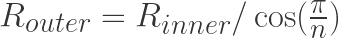
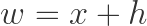
The faceting error comes about from CAD programs using the outer circumcircle as the basis for the radius of the polygon.
For a hole you actually need to use the smaller incircle radius. To convert from the incircle radius for a regular polygon with n sides you simply apply the following:
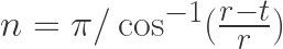
This formula can actually be quite useful for calculating the number of sides needed given a radius and tolerance. Simply re-arrange in terms of n to give:
For values of r between 1mm and 20mm, and a tolerance of 0.1mm this gives values for n ranging between 7, and 23. This brings me on to segment pausing. I find it hard to believe that current reprap electronics will have significant delay when trying to produce 23 short line segments. Nophead dismissed this since his electronics were very low latency, and so will I.
The next factor is arc shrinkage. I found it quite odd that Nophead acknowledged this factor and referenced Adrian Bower’s calculations which compensate for this, but then dismisses it because the numbers come out too small. It occurred to me that Adrian’s calculations are based on a perfect circle, and so the faceting error calculations have to be used in conjunction with arc compensation.
The value for t in this equation needs to be the track width of the extruded path. I wanted to use Slic3r’s formula for this which assumes the area of a track is the same as area of the filament at the nozzle, and that the shape of the track is a rectangle with two semicircles for the sides:
The area at the nozzle is just the area formula for a circle where d is the nozzle diameter:
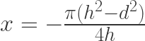
The area of the track is just the sum of a circle area and rectangular area where h is the layer height (which is also the semicircle diameter):
Solving for x when both areas are the same gives:
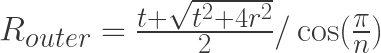
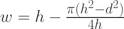
The total track width then is x plus the width of the two semicircles:
Which gives:
Putting this all together I created this new OpenSCAD script:
This file contains bidirectional Unicode text that may be interpreted or compiled differently than what appears below. To review, open the file in an editor that reveals hidden Unicode characters.
Learn more about bidirectional Unicode characters
Every drill bit fit snugly in the hole it was meant for. Even the small sizes worked surprisingly going down to a 1mm drill bit. But wait… I haven’t accounted for corner cutting. Well this is the aspect where I think I am going to have to disagree with Nophead. Not least because I didn’t account for it in my test above, but also because the assumption is that the filament is being stretched as it goes round corners, and this seems wrong to me. Surely the filament should be being extruded at a rate equal to the motion of the nozzle so that no stretching should occur. In fact in contrary to this Slic3r utilises a faster motion than the extrude rate to deliberately stretch the filament for making bridges, but not during normal perimeter generation. Its odd because Nophead says this is this is the dominant effect on his machines, and is the main justification for using less facets for the holes. Perhaps his extrusion rate is lower and so the filament does get stretched.
For holes below 2mm in diameter Nophead’s formula says you need 4, or 3 facets, which are not really holes at all. I would argue that smaller holes require a higher tolerance to produce accurate results, and from the formula for n above that means you need more facets, not less.
You can really notice the how the difference in facets effects the quality of the holes in the two test pieces:
As a final note I thought its worth mentioning that even a machined hole will be considered an interference fit (tight) if its drilled at the same diameter as the shaft or bolt that its intended for. For this reason a table of clearance holes is used
For a while now I have been using VirtualBox to run various windows guest operating systems on my Linux host. One thing that I have always been wary of when using them is how the disk image gradually grows over time. This is because on the host operating system the disk container uses a sparse file so that the virtual disk can appear to be bigger than it actually is, but it can only do this when the guest operating system is not using the space, and the data is effectively set to zero. When you delete a file on the guest operating system it doesn’t bother to set the file contents back to zero, it just removes the record of where the files data was located.
This is not really a problem and most people know that you can use a tool such as sysinternals SDelete to zero the free space. Then using the command
vboxmanage modifyhd --compact <diskimage.vdi>
the space can be reclaimed.
However in windows there is one file in particular called pagefile.sys (also known as the swap file) that is constantly being written to and then subsequently erased. Its possible that windows does this intelligently and re-uses the same sectors of the virtual disk for the pagefile, but it seems more likely to me that windows doesn’t do this, after all it isn’t aware that its really writing to a virtual disk.
What made sense to me was to create a second virtual disk specifically for the pagefile. I made the second disk image immutable. What this means is that all writes to the disk are stored in a differencing image which is thrown away when the guest machine reboots. Because of this I can ensure that it never gets any bigger. This also has some other advantages.
Firstly I can use the same immutable image for all my Virtual machines. These currently include; Windows XP, Windows 7, Windows 8.1, and Windows 10. Secondly because the image is immutable it allows all guests to use the image while all running at the same time.
Thirdly the fun part, I can host the differencing images to the immutable base image in tmpfs meaning that the guests get the advantage of having very fast i/o for their pagefile.sys. This is the advantage I like the most because it certainly seems to improve performance.
I have recently been wondering about probability. What is it? Well obviously I know that its “The chance of something happening” but how does probability manifest itself in our universe. Firstly I have made the assumption that for something to happen, you must have a time component. For example a universe with 0 dimensions, and no time, cannot have probability. A point could exist in such a universe, since a point is as Euclid defined “that which has no part” or in other words a point has no dimensions. But in a 0 dimensional space there is no time and so it cannot appear. However in a 1 dimensional universe where the only dimension is temporal, this gives rise to something being able to happen. Admittedly this kind of universe is still only big enough to contain a point, but it can either be there, or not be there. It is a binary universe, and the only event that can ever happen in that universe is the emergence of a point. You could go so far as to say that the entropy of this simple universe starts low, and then at some point becomes high. The trouble with this model is that its time reversible. If you look at this simple universe with time going backwards the point simply exists to start with, and then disappears. So in that sense the temporal dimension is not temporal at all, since it has no arrow of time.
I have decided to move the RapCAD website to a new hosting solution. There are two reasons for this, firstly I don’t see the need any more to host two separate blogs, and secondly because the new solution is cheaper. As a result of this change the bug tracker and forums have gone, (they were not being used anyway) and git hosting has moved primarily to github.
For some reason, with each new major version, Ubuntu keeps changing the location of the minimize maximize and close buttons on the window decorations. Its really annoying because as soon as you get used to one way, they put it back the other way. Once and for all I wanted to fix this problem and have my buttons where they should be, where they have always been (for me this was on the right having come from windows)
I implemented an offset module in RapCAD a while ago. I developed it primarily for calculating print outlines, since the outline must be smaller than the required shape by half the width of the printed filament. The module can also be very useful in other applications such as creating a hollowed out shape. Usually we can create a hollowed out shape simply by performing a difference operation. However when the shape is complex it can be tricky to create a smaller shape of the correct proportion to subtract. In the above image the top 2D shape is created using the offset module, whereas the bottom shape is created using a naive translate and scale technique. Where the scale module simply shrinks the shape uniformly in all directions, the offset module shrinks the shape to the correct proportions offsetting the outline of the shape by the same amount at every point.
Version 0.9.0 is available this month. See the Download Page for details.
This is something that really bugs me. united biscuits manufacture a bar under the brand go ahead!™ boasting that its only 74 calories per slice. The brand name, their marketing campaign and everything about this biscuit, is geared towards this being a healthy option.
“The go ahead! brand offers consumers delicious snacks they can feel good about eating”
However in reality the information being provided isn’t very helpful, and doesn’t allow the consumer to make healthy eating choices at all. Firstly there are two slices per pack, so its really 148 calories. Secondly the bars are tiny only 36g each so you don’t get much. Especially when you consider that for 74 calories you can have 231g of strawberries, or 129g of fat free yoghurt, or 19g of sugar. What the bars should advertise is the calorie density, or calories per 100 gram. In which case its a 417 calorie per 100g bar. Admittedly on the back of the packet such information is provided, but united biscuits as well as many other companies use a loophole in the way they can provide nutrition information to the consumer to make it look like a healthy option when actually it isn’t. Especially when you consider that a Mars bar is 467 calories per 100g. But I don’t have a problem with Mars, they brand their products as confectionery sweets and as such everyone knows they are a treat not to be eaten too often. *
So here is my healthy alternative to go ahead!™ if you just take half the sugar and half the yoghurt you have the equivalent of one slice, and if you take all the strawberries, you have the equivalent of the two slices. So pictured right we have two measly go ahead!™ yoghurt breaks strawberry slices and next to them we have one bowl of strawberries, a huge dollop of yoghurt, and more than two teaspoons of sugar. In addition the go ahead!™ bar has all sorts of other crap in it including:
Strawberry paste 1.5%
Glycerine
Dextrose Monohydrate
Sodium Citrate
Calcium Citrate
Soya Lecithin
Sodium Bicarbonate
Disodium Diphosphate
I am not really sure what any of those things are but my healthy option contains:
Fresh strawberries 50%
Pasteurised Skimmed Cow’s Milk
Sugar
There is no mention of whether the go ahead!™ bar contains any Vitamin C, but being that my option has fresh strawberries in it its packed full of Vitamin C, as strawberries have the most amount of Vitamin C than any other fruit. The yoghurt means it is also packed full of protein and live active yoghurt cultures (L. Bulgaricus, S. Thermophilus, L. Acidophilus, Bifidus, L. Casei). I know which I would rather eat, so I did. It was delicious. The go ahead!™ bar went in the bin.
*Previously Mars had an questionable advertising campaign slogan “A Mars a day helps you work, rest and play”, but the current slogan is simply “Work rest play your part for England” which I think is a responsible way of promoting sport and exercise using the brand
Breaking with tradition I have decided to do a release on the 16th this month instead of the 8th. Then the following release I plan to do on the 32nd, which of course doesn’t exist so it will actually be the 1st of month. The reason for this is just for fun, and because I would like to have my releases go out on the first day of the month 😉
Changes
Implemented amf export feature. – Thanks to Steve Kelly for his work on this
Allow range values to be treated as though they are vector values.
Implemented preferences for edge and vertex size.
Added simple about box dialog that displays the RapCAD version number.
Improved the tool tips in main window tool bar.
Improve memory management for values.
Improvements to array concatenation code and some tests.
Fixed some defeferenced null pointer exceptions in polygon.
Documentation Improvements.
Added some more examples
Licensing updated.
Version 0.8.0 is available this month. See the Download Page for details.